College Projects
The following projects are separated into categories.
Design Projects
Music for the Deaf (Part 1)
For my senior capstone design project, five of us decide to work with the Deaf/Hard of Hearing community to create a device that empowers their "listening" of music. Some background:
- Deaf/Hard of Hearing people experience sound through vibration
- The go to concerts, dance club with vibration floors, and even hold a balloon to feel/amplify vibrations
- Studies show the part of their brain that processes vibration includes part of [hearing] people's brain that processes sound
Our goal? To make music (specifically the musical experience) more easily available for the Dead/Hard of Hearing community. Rather than going to loud concert halls or dance clubs, what if they could experience music in the comfort of their own homes? Our idea is to create a wearable device with several motors/actuators the vibrate to the beat of a musical input.
To help you understand what we're doing, imagine a music visualizer (below) but instead of the visual aspect, we're creating a
vibrational equivalent.
What was my role? Well I was the team lead - I put the team together, wrote the project proposal, scheduled group meetings, and delegated tasks. For the project specifically, my role was research, customer outreach, and mechanical testing. This is all for part 1 of capstone, since Northeastern capstone is split into a summer semester (May and June 2018) and then a spring semester (January - May 2019). At the end of capstone 1, we did not get to design/prototype the idea, we would do that when we went back to classes in January 2019. If you are curious to see what we had done up to this point (our research paper), click here.
Music for the Deaf (Part 2)
After six months, returning from our last co-op and back in classes, we were ready to put all our efforts to make this project a
reality. At this point, we envisioned a vest with strategically placed exciters (low volume speakers) that could capture and playback all the parts of a music file. This would effectively allow a deaf person to 'experience' music through vibrations.
Early in February, we reached out to various people in the local deaf community so see if anyone wanted to volunteer to test our prototype and give us feedback. We were extremely lucky that one of Northeastern's deaf professors, Laurie, responded with her
interest and excitement to take part in our project.
We first met with Laurie late February to show her our initial designs and to get her feedback in it. Laurie gave us many great ideas, the most important of which was that she wanted to be able to move with the device on.
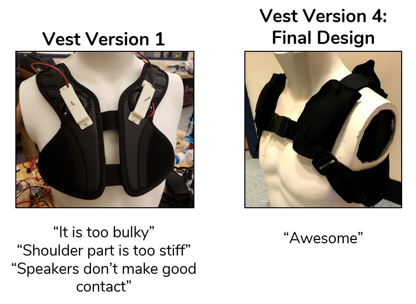
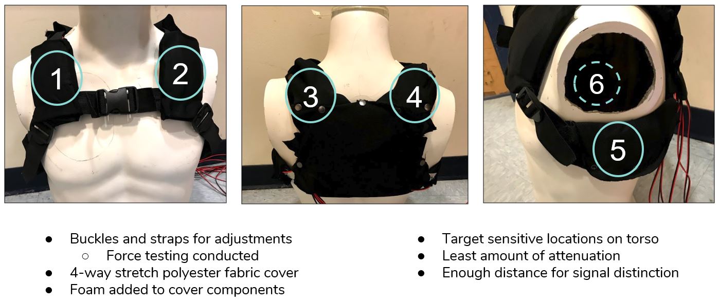
We met Laurie three more times before our final Capstone presentation, each time iterating a prototype using her feedback. Our initial prototype and our fourth (and final) vest prototype is shown below (bottom left). To the right is the exciter placement on the final vest:
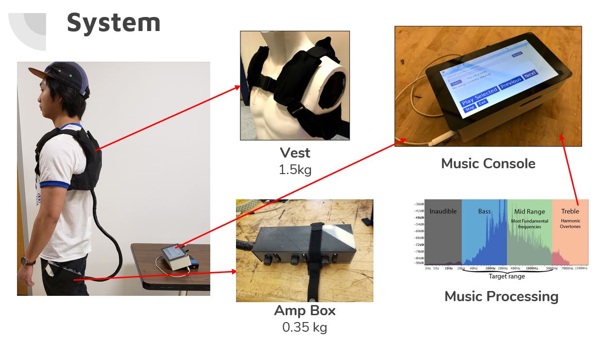
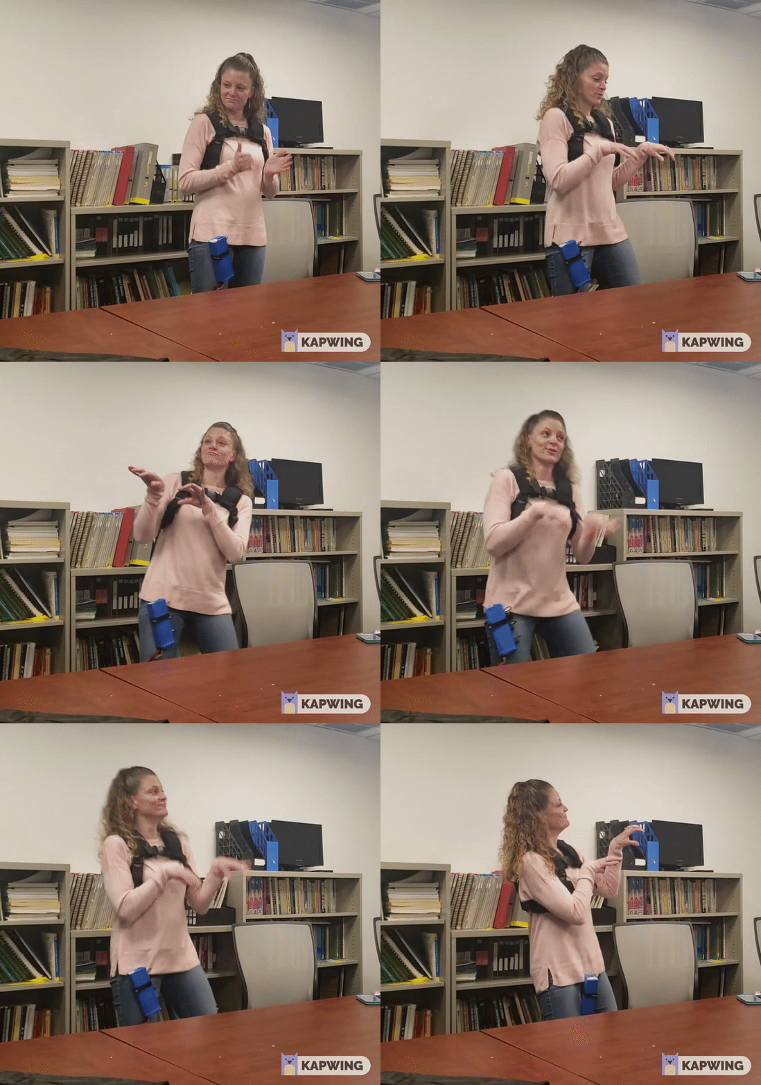
The vest was only one component of our final system. In addition to the vest, there is an amplifier box to adjust the vibrations and a music console to control the song that is begin played. You can see this below on the left. On the right we have a video of Laurie using the device and dancing to Micheal Jackson's Thriller (keep in mind she is deaf). She was very happy to be able to recognize and dance to the song.
Laurie being happy with the device was only one part of our project - we still had our final report and final presentation left. Fast forward two weeks later, after everything was said and done, we were at the awards ceremony, where the Dean of Engineering was giving awards for the best capstone projects. We didn't expect any award since there were projects way cooler than ours, so imagine our surprise when we won the award for "Greatest Potential Impact". We were ecstatic!
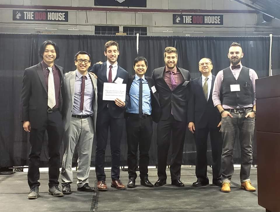
We were very happy with how our capstone turned out. It was cool and all that we got the award, but it was a greater feeling that we made a difference in Laurie's life!
You might be wondering what my role during this part of capstone was, so I'll tell you: It was designing all the CAD models for the attachments and enclosures, administrative tasks (scheduling meetings, keeping deadlines and accountability), and supporting my team with hardware testing. I gained a lot of experience throughout capstone, namely in design, testing, and leadership. All in all, it was a great experience, especially because I got to work with such a great team!
Piezoelectric Model
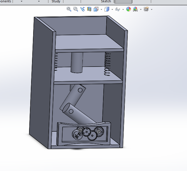
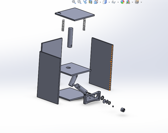
For my freshman engineering design class, we had a final project in which we had to make something that demonstrated energy conversion (electrical, mechanical, chemical, etc). My group made a device based on the piezoelectric effect, which is essentially mechanical to electrical energy conversion. Here is our take on it:
*** The video might not work on mobile devices
I helped my group build the device, but my main role was to draw it in SolidWorks. This was no easy task, as this was done about six weeks after my initial exposure to SolidWorks in the class. The class helped me learn the basics, but it was no way in depth enough for me to draw this device. That's when I turned to YouTube.
As a comparison, the picture on the right was the SolidWorks test for that class.
Six hours later...
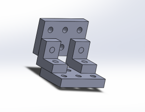
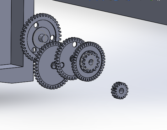
I'm really proud of my final product. I took something that I helped create, and drew the whole thing in a program I just learned. Granted, it took a lot of time to figure things out and watch videos on YouTube, but the end result was well worth it. I mean, look at the level of detail of the gears.
So what does this show? I am able to learn things independently, I go above and beyond what is expected to do exceptional work, and I pay great attention to detail.
Research Project
Comparison of Commercial Solar (PV) Systems
For my graduate power electronics class, we (a group of 3) were assigned a project to find an application of power electronics, and write a research paper on that topic. We chose the power electronics of commercial PV systems, specifically inverters and their different layouts in current PV systems - central inverters, DC-DC optimization to a central inverter, and microinverters - to see which layout was the most cost effective under different types of shading.
For those of you who are not familiar with commercial PV systems, the three layouts we looked at were:
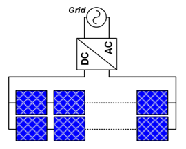
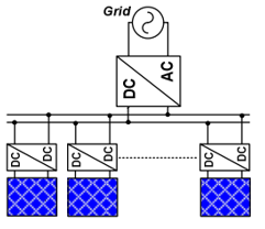
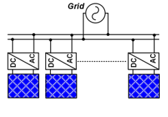
Left to right: Central Inverter, DC-DC Optimization, Microinverter
I was the lead in the project, so I set up the meetings and delegated roles for the project. I gave myself the role of researching the three PV systems and analyzing data output from the simulations. I gave them the role of researching and creating the models. I choose these roles based on our strengths.
For my research, I had to go through a ton of resources (internet, textbooks, published papers) to get the information we needed, and then I taught them about my findings. With that information, they created models of the systems in Simulink. They then taught me how to make sense of the model and gather output (I didn't know how to use Simulink at the time).
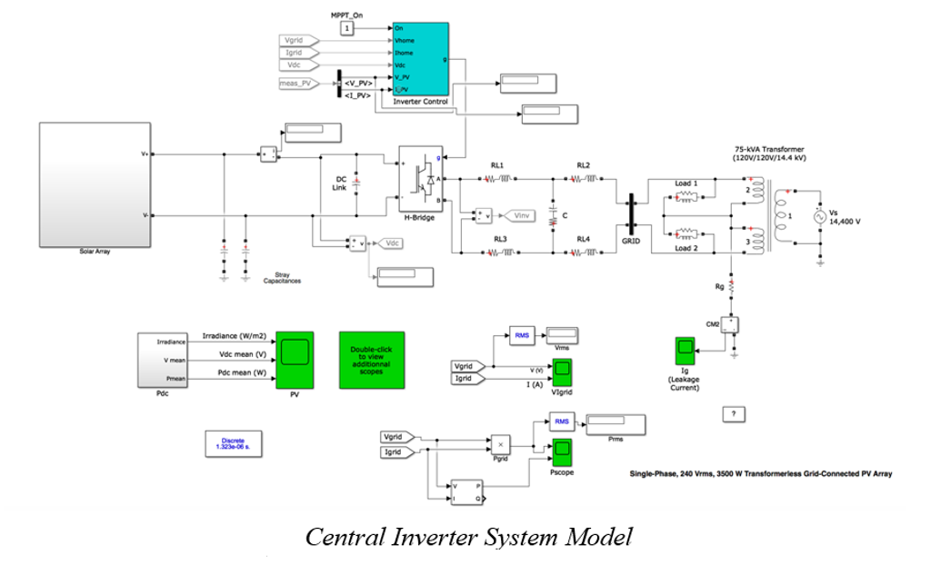
To give you an example, here is our modified Simulink model for a central inverter layout (credit to Mathworks for the original model):
With the three models completed, I gathered all the output data and did the analysis, comparing cost with shaded performance. Then I finalized the paper. You can read it here.
This project shows that I can collaborate with others to accomplish a common goal while taking into account people's strengths and weaknesses when delegating tasks, learn/gather information quickly, and analyze data to draw conclusions and make recommendations. Overall this project was a success!
Robotics Project
Forward and Inverse Kinematics
For my graduate robot mechanics and control class, we had two projects. The first one was forward and inverse kinematics, the second one was control and path planning. For this first project, I had to mathematically and physically model a PUMA 500 Arm to predict the end effector position given joint rotation angles (forward kinematics) and predict joint rotation angles based on end effector position (inverse kinematics).
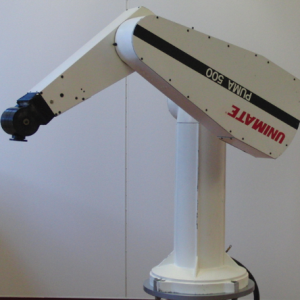
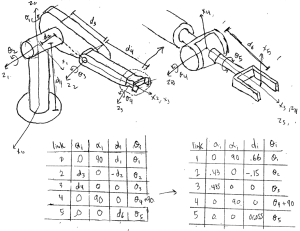
The left picture is the an actual Puma 500 and the right picture is a handrawn PUMA using DH notation, which represent the configuration of the Puma 500. The DH table under the drawing is used to derive the mathematical model of the PUMA. The actual mathematical model is a very large matrix so it is not shown.
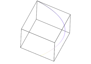
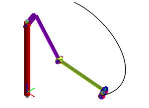
The picture on the left shows the path the robot end effector makes by starting at point (400,400,1000) and ending at (500,300,100) which were the defined project parameters. This path was made by plugging the mathematical model in Maple. The picture on the right was a physical model I made using RoboAnalyzer. The black line is the same path as the maple graph. This consistency shows that the mathematical model was correct.
Path Planning and Control
For the second project, I had to mathematically model a real 2 DOF robot arm and make it move in a parabola, by controlling the voltage of the driving motors.
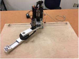
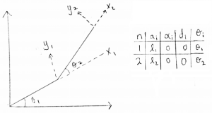
The left picture is the 2DOF Arm and the right picture is a model of the Arm, using DH notation to create the mathematical model.
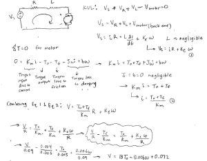
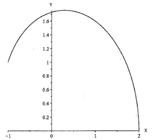
Since the motor voltage is the driving signal, a relationship between joint angle rotation and driving voltage was needed (left picture). This was done using the solved forward kinematics and the armature circuit (left picture). Then the inverse kinematics allowed me to relate the joint angle rotation to the end effector potion. The right picture shows the parabolic path of the end effector (output) given the driving voltage (input).
The driving voltage function was put on a script and ran on the actual 2DOF Arm, and the path resembled a parabolic shape, although not precisely since there was no controller.
So why did I include these projects in my portfolio? Because they show I can model a real life system, perform simulations, and ultimately drive the system based on the simulations. Also because robots are cool!
